Whilst on the course for my foundation exam in February, I still had the word’s of John Mulye G0VEH ringing in my ears.. “Why go out and buy a load of ready-made rubbish when you can make your own with some wire!”. He was of course referring to antennas, a subject which really interests me, as no matter how much you spend on your transceiver, it is only as good as the antenna you attach to it.. oh, and the feeder!
I have started out by using a ½ size G5RV which is mounted on a temporary basis on tripod in the corner of the garden, lashed with bungees to a disused barbecue and only about 8ft of the ground. I enjoy a good takeoff to Europe, but unfortunately, with the aerial being so low, it is totally blocked to the North & East which makes the Americas a bit of a bit of a challenge!
The G5RV only works on 40, 20 and 10 Metres pretty much, so I need something that will perform better and give me more bands. I started to hit the books and consider different designs. My favourite to try would be the Hexabeam, which looks reasonably straightforward to construct (once you master the distribution system on the hub), but it is directional, which would require me to spend out on rotator. I thought that this might be too adventurous for a first project, so instead chose the Cobwebb.
I was further confused by the options available.. The G3TPW is the well known one. It is well proven and works well on 14, 18, 21, 24 and 28MHz, It has a great truly horizontal polarisation and confined electric field which reduces EMC issues. It does use a 50 ohm connection and integral choke balun. The drawback was as far as I could see was the fact it uses twin flex in a square halo configuration of folded dipoles. The difficulty for me is the gamma tee matches which requires the insulation to be split on the wires and for the two cores to be joined at precise measurements along the radiators. The problem with this arrangement is that it is very difficult to make an adjustment when you have already stripped the wire in one place!
Never fear though, I found an alternate design from G3TXQ which addressed some of my issues. It uses single core conductors, which are matched to the feeder by a 1:4 Guanella Balun. I have never tried winding baluns before, so I thought this might be a challenge. I have never been that good at fabrication, but I bought myself some handy tools (A giant Dremmel style rotary tool has proved to be a godsend) and cracked on..
I have sourced a few items for my build from the dreaded ebay. Fibreglass spreaders from Amtools, Elasticated mini bungee and spring toggles. The rest of the materials came from a well known DIY store.
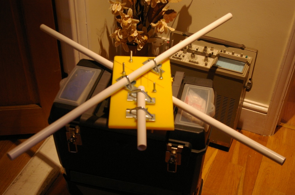 First thing to make was the hub. I have seen kits for spreaders which looked everything from really professional to really naff, and decided to make my own. I raided the kitchen and used a surplus to requirements plastic chopping board for the base. I got some u bolts and gripping plates from the DIY shop, along with some 21mm overflow plastic pipe. I drilled the holes for the U bolts and clamped on the overflow pipe which I was using as receivers for the fibreglass spreaders. The fibreglass poles slide in nice and snug and are held firm when the U bolts are tightened, the pressure being distributed on the plastic pipe which grips the poles and prevents them from being damaged from the pressure. Next up is to build the balun and the box to which all the wires connect. The idea I used was the same as G3TXQ, to use a piece of single sided PCB, cut a strip out of the centre and mount it in the box, as shown in the picture.
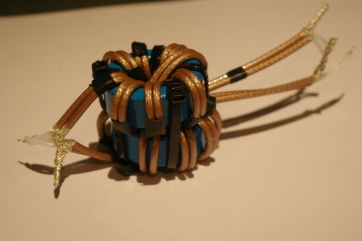 The Guanella Balun was fun. The main problem was not the toroids (2 cores required), which I managed to pick up at a rally, but the RG316 coax used to wind on them. The Balun is an interesting design to match the 12 Ohms of the antenna to match to the 50 Ohm feeder. The design would use 25 Ohm coax, but as this is difficult to obtain, two lengths of 50 Ohm coax are used in parallel. The two baluns are then joined in parallel at the antenna end and series the feed end. This provides not just the impedance transformation, but a good choke action as well. I had considered buying the Balun kit from Amtools, but it was a scramble wound design and I felt it would not provide the same performance as the one using the coax. It also did not look as neat.
Below is a picture of the connector box along with the PCB ‘bus bars’ and the bolts that go through the case ready for connection to the antenna elements.
 The box is shown with the balun ‘offered up’ in place before it is permanently fitted in. I will be adding some insulation between the balun and the PCB, to ensure that the bolt heads do not dig into the coax on the balun.
Next is the mounting of the box on the balun, the cutting of the radials and stringing them on the spreaders.
The antenna was tested first using my latest acquisition, a Racal 12m mast before being mounted on the top of the house. I was testing for SWR and ability for the antenna to null out interference from next-doors plasma TV!
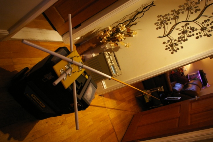 Here is a picture of the hub with just one of the telescopic fibreglass spreaders in place. I can’t put the whole thing together in the house, even if it only has a swinging radius of 8ft!
Next, final assembly and testing. For this I dragged out my newly acquired 12m mast, thrown up in haste in the back garden. This was going to prove a costly mistake as I will explain later. The idea was just to have something to mount the antenna on whilst I tested and adjusted it.

Above is the antenna mounted on the mast with the wires strung on the spreaders. I have not even cut the tails off the cable ties yet as I might want to adjust the spacing.
I measured the resonance of the antenna at both 6ft and at about 30ft.
|
Centre Frequency (6ft) |
Minimum SWR (6ft) |
Centre Frequency (30ft) |
Minimum SWR (30ft) |
|
14.004 |
1.1:1 |
13.946 |
1.2:1 |
|
17.978 |
1.2:1 |
17.960 |
1.1:1 |
|
20.723 |
1.2:1 |
20.725 |
1.2:1 |
|
24.552 |
1.1:1 |
24.571 |
1.1:1 |
|
28.140 |
1.1:1 |
28.151 |
1.1:1 |
All that is required is some judicious adjustment to the 17m & 15m radiators.
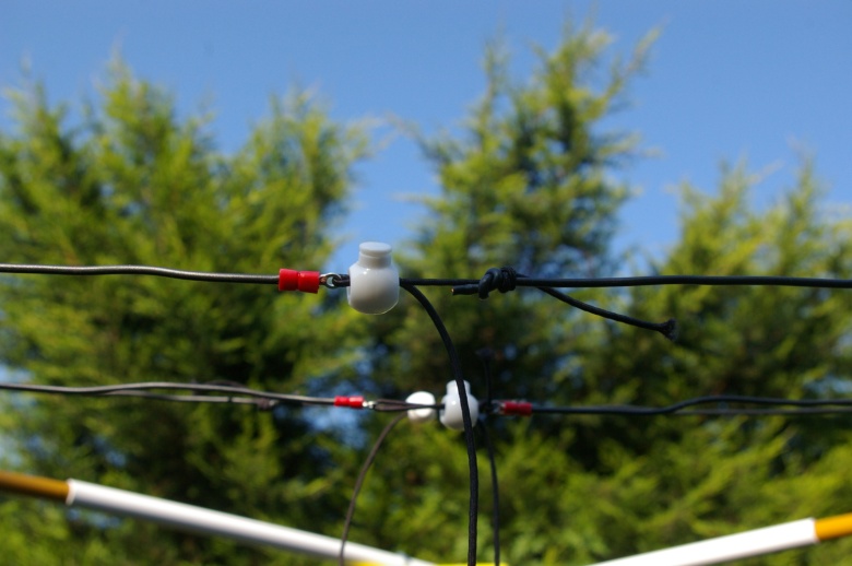 The cables were tensioned with miniature bungees, and secured with spring toggles (see left). This allows the wires to be held in tension and adjusted easily. It also allows for quick de-rigging if required for mobile use.
I put the antenna online via a two way switch to allow comparison to the old faithful ½ size G5RV, and the difference was noticeable.
Just switching between one and the other, it was obvious that the Cobwebb was either totally deaf and not working correctly or was just very much quieter than my ½ size G5RV. Where I was getting up to S6 of noise from the wire antenna, the cobweb was showing me a paltry S2-3! What I realised quite quickly was that the Cobwebb was much quieter than the wire and exhibited much better signal reception. Stations received at S3-4 were up to S9 on the Cobwebb. Also the built in ATU in my IC746 was not finding tuning it a challenge at all (before trimming the antenna for tuning)!

Time for the first real test, how does it transmit? First up it was an SSB contact into Croatia 5:9!! Wow, I am well impressed. Next, let’s try data. Where I was struggling due to interference from my next door neighbours plasma TV, I now have their TV attenuated (although not completely gone) and my first contact into Lichtenstein asks me what antenna I am using.. I tell him that I have just finished building a Cobwebb, to which he replies “We are also going to be making antennas next week…. A Cobwebb antenna”!
After this, I had an accident with my mast and snapped one of the spreaders! Mark 2 is now on the drawing board and will be seen on my house shortly! This will also include an extra element for 50MHz
More soon!!!
73
Dave M0MBD / 2E0DDH
Email: m0mbd@lefars.org.uk
29/07/2013 Update – some photos of the MKII portable Cobwebb design in use at G100RSGB on 28th July here